Scooter was controlled using two Arduino Uno’s communicating on a serial network. Check out all 3134 lines of our source code on GitHub here.


Master/Slave model: two key advantages
- Additional i/o from two boards required to run Scooter’s 6 servo motors, 2 dc motors, stepper motor, read 8 analog sensors and sample IR signal frequency.
- Blocking or demanding tasks (i.e controlling a stepper, sampling IR, tape following, writing to servos…) can be done in parallel.
Master Functions:
- Runs core logic
- Controls DC motors for drivetrain
- Samples IR signal
- Receives 6 analog reflective sensor inputs for tape and edge detection
- Sends/receives serial commands to the slave
Slave functions:
- Parses serial information from the master into 33 unique commands
- Controls both claws
- Controls bridge dropping mechanism
- Controls lift stepper motor
- Receives analog input from 2 transmissive object sensors
- Communicates back to master when objects have been detected
For its core logic, the master Arduino implements a finite state machine model, which on a high level resembles the block diagram below.
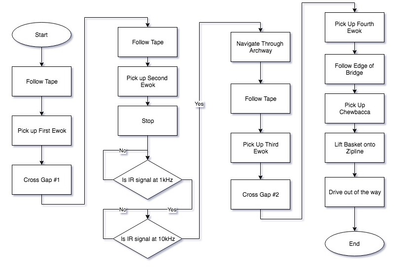
What is not shown are what conditions prompt Scooter to transition from one state to the next, and what other possible logic progressions he could take if he has encountered an error.
In general, Scooter will transition from one state to the next based on three possible outcomes:
- An expected sensor input
- An unexpected sensor input
- A timeout
As an example, we can examine Scooter’s behaviour when he goes to pick up the third Ewok (expected to be somewhere near the black circle below)
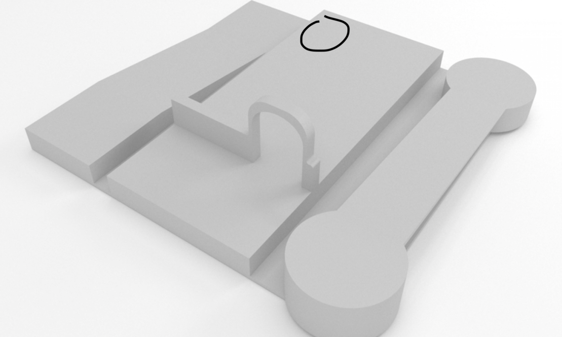
After detecting the appropriate IR signal to indicate safe passage through the archway, Scooter will use analog values of the reflectance of his four tape sensors to continuously calculate the location of a strip of black tape. Using the setpoint error of the tape location, Scooter can smoothly follow the tape using a PID algorithm tuned for his particular transfer behaviour via the Ziegler–Nichols method.
When the left object sensor identifies something inside the claw it will communicate this back to the master. The master will then compare this information with its current knowledge of its location in the course. If everything looks correct the master will stop the DC motors and will send a message back to the slave, telling him to close his left claw, lift the object and drop it into his basket.
Scooter following tape while looking for the third Ewok
This behavioural progression works, but is not all that robust on its own. If, for example, Scooter failed to locate the third Ewok, knocked it over, or any number of other things went wrong, Scooter would drive over the edge!
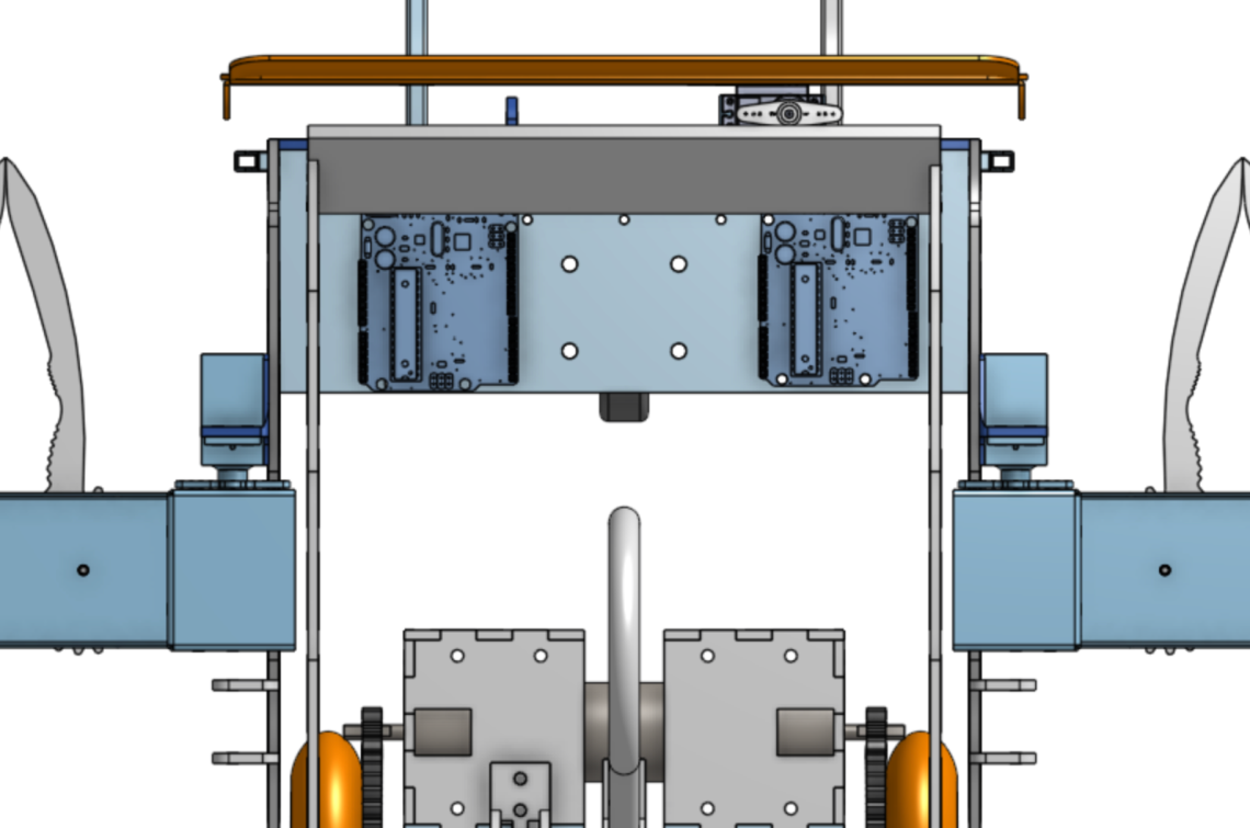
For this and many other reasons, Scooter is equipped with two edge sensors (circled in blue)
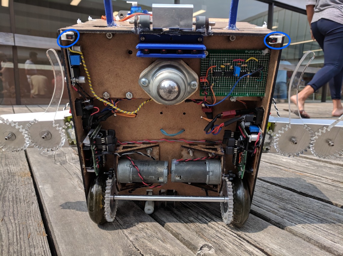
If Scooter suddenly notices a large drop in reflectance of either of his two edge sensors, he has overshot his target and must stop, back up, and move on with the rest of the course.
In General, Scooter’s software model was always designed for peak performance in the optimal case, but was supported by critical alternate/error conditions that greatly improved his reliability.
Software Model
Scooter’s software model was built as a fully deterministic finite state machine. Each state was its own object that extended and abstract class with six distinct methods.
- Start: Called once at the beginning of the state
- Loop: Called sequentially until and transition condition is reached
- End: Called once after a transition condition is reached
- Transition: Called every loop to determine if the state should end by an expected condition. Indicates what state to go to next.
- Alternate Transition: Called every loop to determine if the state should end by an alternate condition. Indicates what state to go to next.
- Error: Called every loop to determine if the state should end by an unexpected condition. Indicates what state to go to next.
See the state source code here. The automation of state creation was implemented through a batch script that generated a state with a command-line-argument-passed name, and pre populated the state methods.
A Custom Built Complier
In every transition/alternate/error condition method, there is an XML style tag that indicates what state the code should move to when the condition is reached. To automate and abstract the process of making sure the transitioning was easily modifiable and implemented correctly, we designed and built our own mini compiler using Python. The compiler’s job was to identify all the state files in our directory, map out their transitional connectivity through their tags as a directed graph, and generate a main file that ensured correctness of all state transitions. Such a high level of abstraction certainly saved us hours of debugging and kept our code very modular and clean.
