DC Motor Drivers
To drive our DC motors, we built two digital H-Bridges. The motors were driven using 5V PWM waveforms, amplified to 15V off an external Li-Po battery. A quad high-side MOSFET Driver was used on each H-Bridge to enhance the switching capabilities of four N-Channel MOSFETs without the need of any external components.
H-Bridge schematic
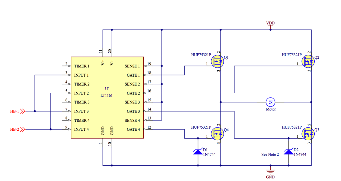
Both H-Bridges were attachable and removable from custom docking stations. This feature was extremely useful in speeding up troubleshooting and part replacement.


Tape/Edge Sensors
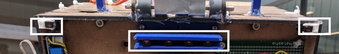

The four sensors in the center all return analog values proportional to their reflectance with the surface below them. By placing the sensors high enough above the ground, a very good estimate can be calculated for the location of a black piece of electrical tape on a white surface. By using the continuously updating error of the current tape position from a setpoint, Scooter implement a PID algorithm to smoothly follow tape.
The two sensors on either edge were used to detect gaps and follow the edge of a bridge in the final stage of the course.
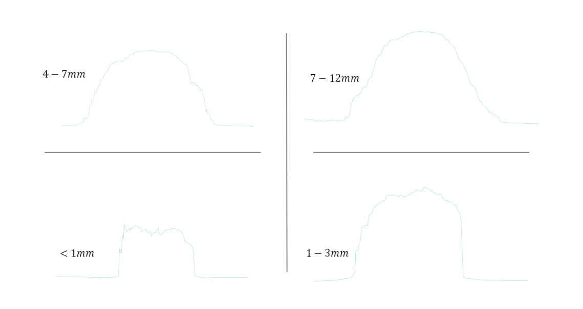
In the early design phase, an experiment was performed to identify how high off the surface reflective sensors should be placed to maximize sensing linearity for the zone where the sensor was neither fully on nor off the tape.
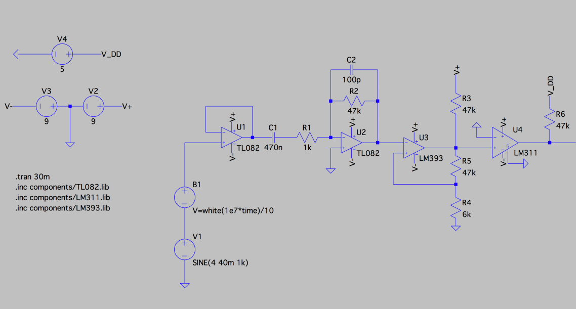
IR Detection
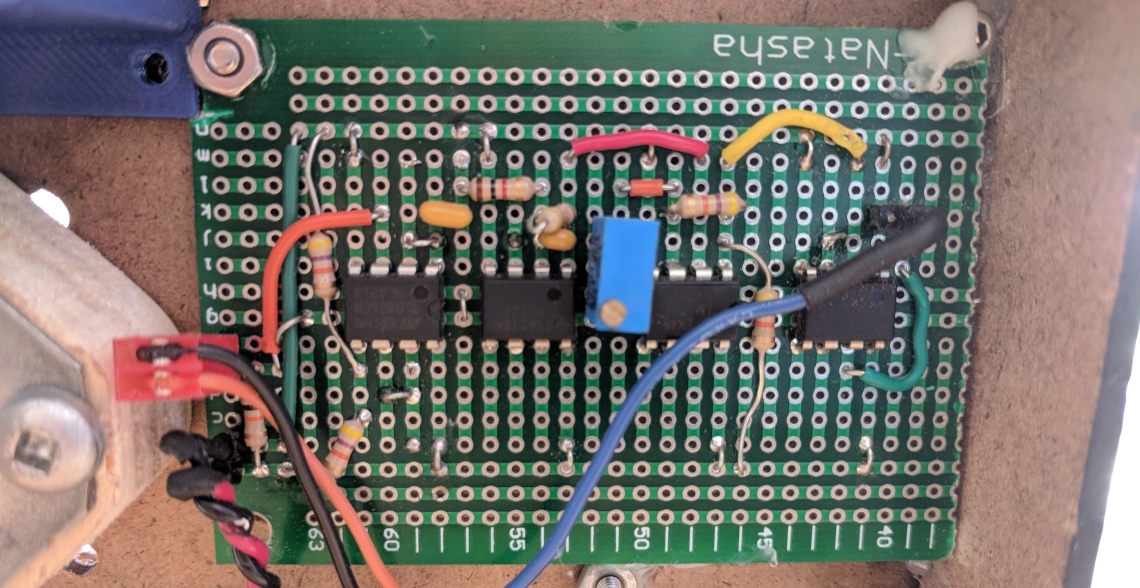
To safely pass through the a gate, Scooter needed to distinguish between a 1 kHz and a 10 kHz modulated IR signal. We designed a circuit to receive a small IR signal from a QSD photo transistor, amplify this signal, remove noise through a bandpass filter, then finally rectify the signal into a 5V square wave. This wave could then be read by our Arduino, and its exact frequency calculated in under 10ms from a range of across the room.
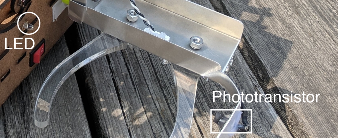
Object Detection

We mounted an infrared LED to the chassis and a shielded IR photo transistor to the far side of the claw giving Scooter a 4 inch wide band on either side to locate objects. When an object enters the claw, the photo transistor’s pulled up voltage spikes dramatically and the object is grabbed and placed in Scooter’s basket. See our section on software for a detailed description of how Scooter processes these signals and controls his claws.