Chassis & Drivetrain
Scooter’s chassis is made of laser cut high-density fiberboard. It was designed to give as much space for the Ewoks as possible. Scooter is driven by two 12V geared Barber-Colman DC motors, which each control a scooter wheel at the back of the chassis. He is supported at the front by a ball transfer, to provide simple, omnidirectional steering.
Our entire robot was designed and modeled using the online CAD software OnShape. View the project in your browser here.


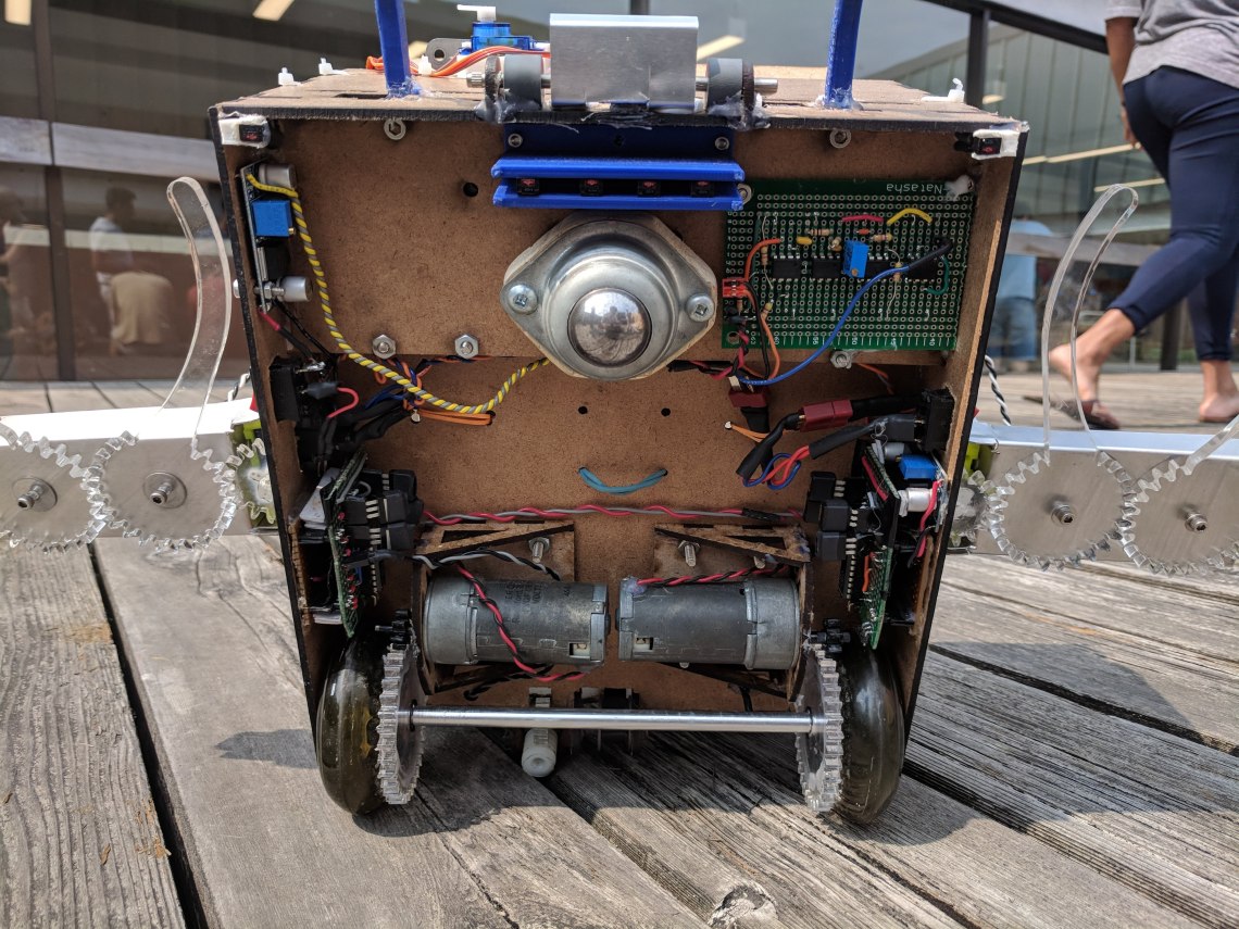
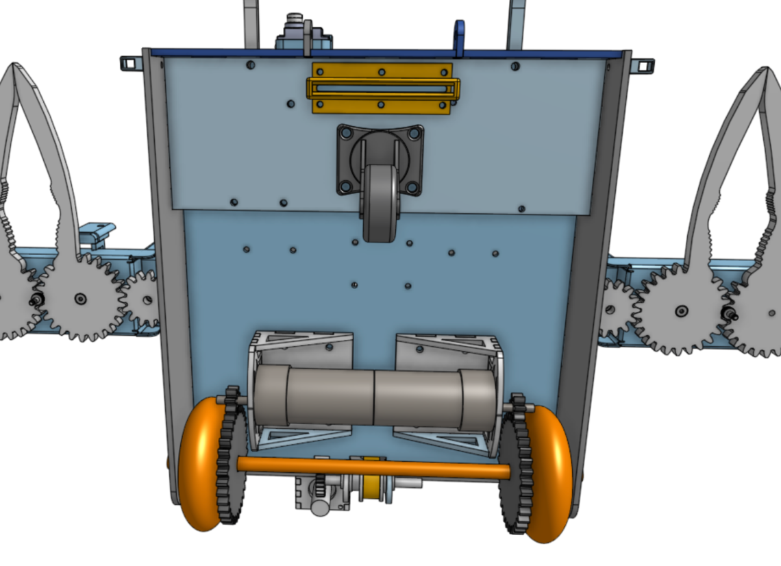
One notable difference between the last two photos is the front drive system. Originally, we used a caster mounted wheel, but experienced problems when turning too abruptly or backing up due to the wheel not being able to line up quickly enough with the intended direction of motion.
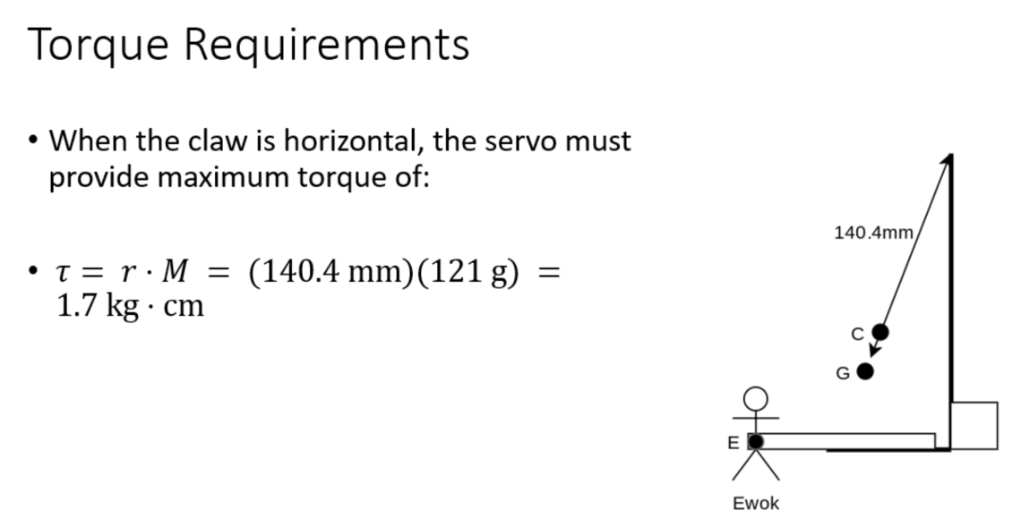
Claws
Scooter has a claw on either side of the chassis to pick up the stuffed animals. The claws are made of waterjet cut, machine bent aluminum sheet metal and laser cut acrylic. The claws are controlled by two servos, one which opens and closes the claws to grab onto the Ewoks, and the other to pivot the claw arm 180 degrees to drop the Ewoks into the basket. The claw design and positioning made it essentially impossible to miss the Ewoks yet was unique in the class.


Design Challenges
One of the biggest problems we had with the claws was that the gears from the servo and claw did not always mesh properly, and often got jammed. This was caused by the servo being weakly mounted on a piece of sheet metal and being free to move around. To fix this problem we designed and 3D printed a mount out of PLA that rigidly held the motor in place and ensured perfect meshing.


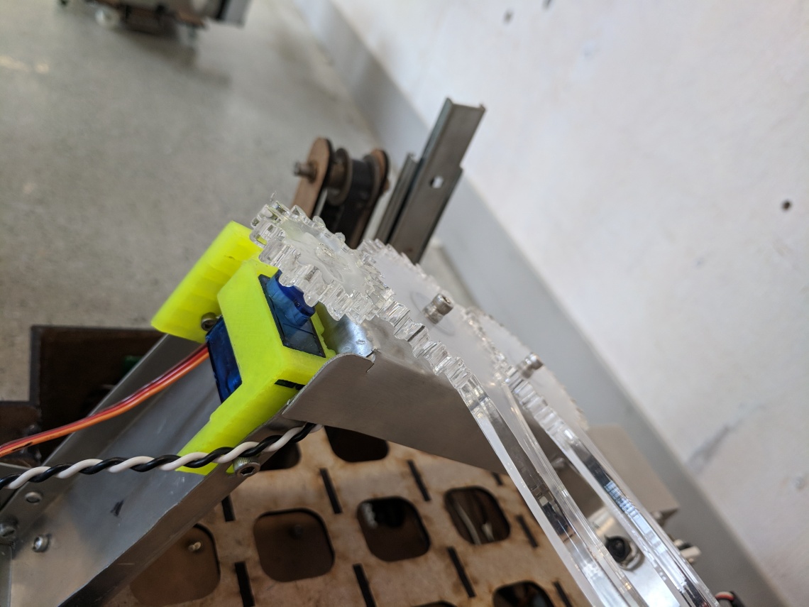
3D printed servo mount
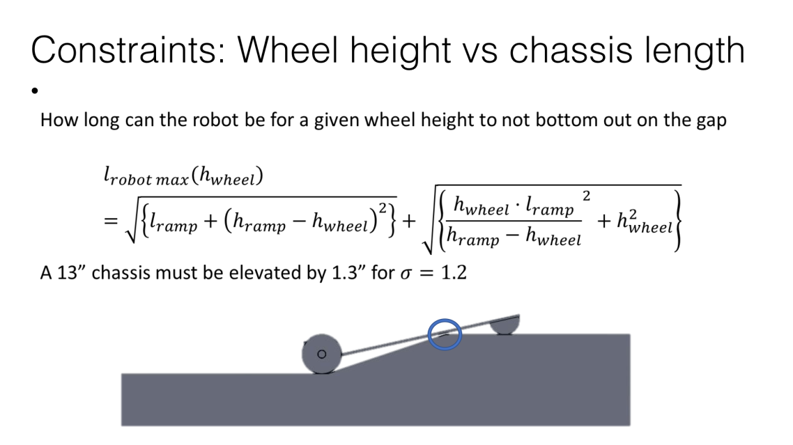
Crossing Gaps
To cross the two 6” gaps, Scooter carries two bridges made of waterjet aluminum sheet metal. The deployment of the bridges is controlled by two servos, one to restrain the bridges when they are not being used and one to push the bridges off the chassis. The placement of the bridges is controlled by two 3D printed hooks.
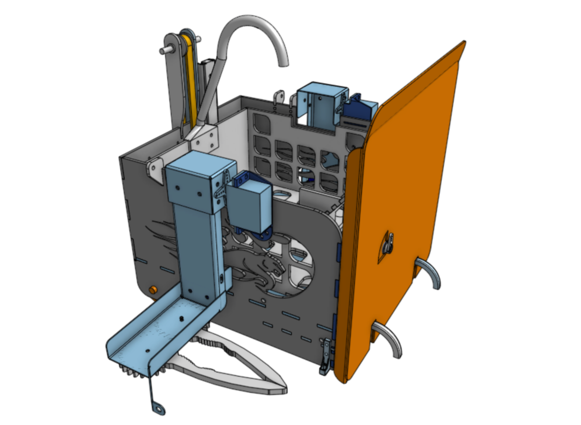
On the left is a servo that turns CW to push the first bridge (through a slot in the second), and turns CCW to push the second. On the right is a servo that holds either both bridges in place, just the second one, or neither.


Lift and Basket
Scooter keeps all the Ewoks in a hardboard/acrylic basket which rests on a raisable platform. The platform is raised and lowered by a stepper motor via by a worm gear that drives a small gear attached to a timing pulley. The basket has a 3D printed hook to slide down the zip line to the starting area.
An interesting challenged was getting the lift to raise at a reasonable speed. We learned that stepper motors tend to stall easily when accelerated too abruptly. By tuning the pulse frequency into the stepper driver to control the exact acceleration, we were able to increase the speed by over 2 times of the maximum possible via a constant velocity approach.
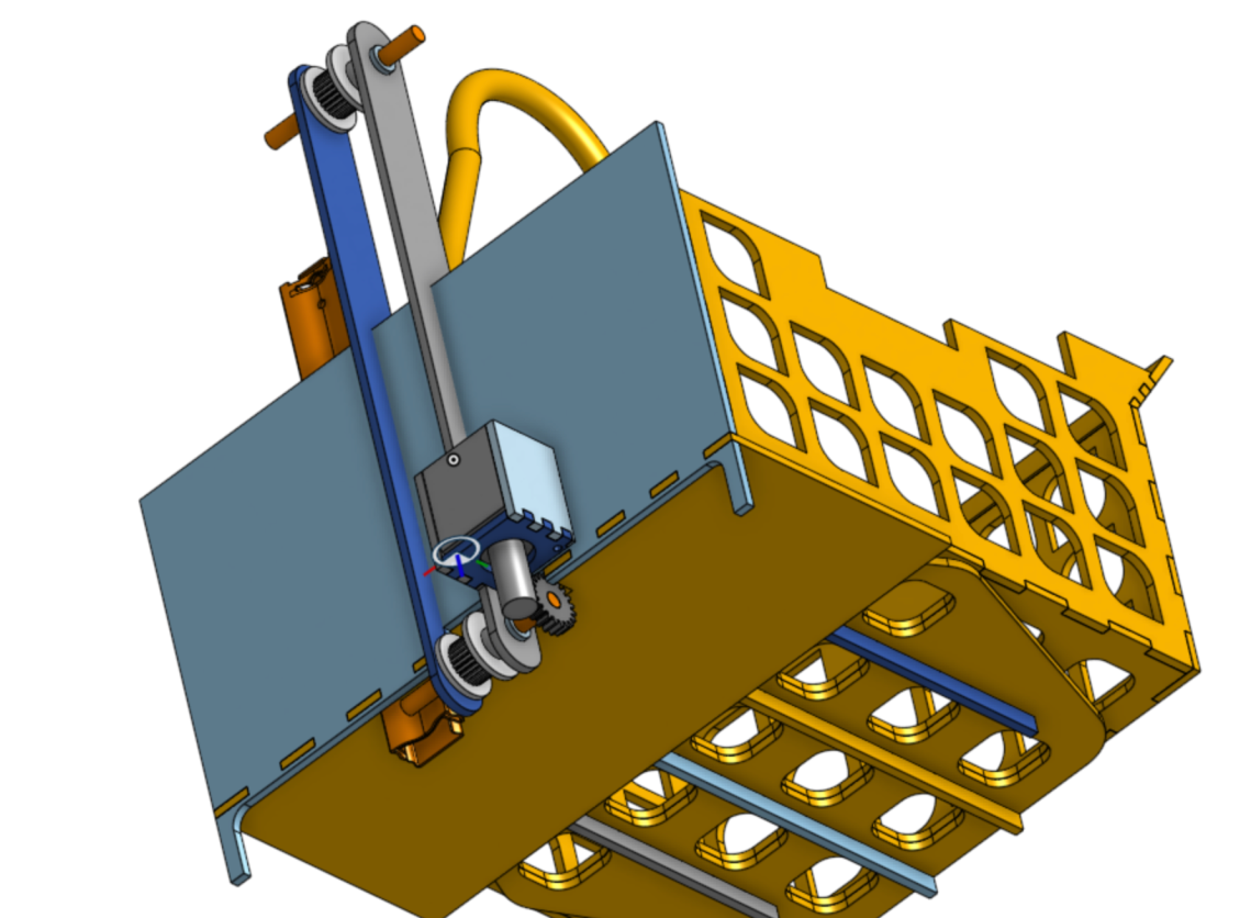
A small acrylic gear was laser cut to mesh with the white worm gear on the stepper, creating a gearing ratio of 22:1. This greatly reduced the motor size and power requirements of our lift. It also provided holding torque so the platform could be raised and held in place without falling back down.
 The 3d printed blue piece on the back is a specially designed, adjustable timing belt tensioner. This tool provided significant improvements with the speed of the lift and ensured that the timing belt would not skip steps under heavier loads.

Lift Design Challenges
For a first prototype, the linear bearing was placed opposite to the timing belt in an attempt to provide better support for the platform. What we did not realize was that the linear bearing was not weightless, and thus created a significant torque on the left side of the platform attached to the timing belt. Since the belt was not perfectly rigid, it had a limited capacity to produce a reaction moment. As a result, the left side of the platform would rapidly lift above the right. A spring (seen on the right) was used to mitigate this effect, but ultimately was not enough, and the linear bearing was moved closer to the timing belt to decrease the torque.
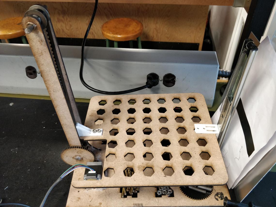
The lift was then integrated into the back wall of the chassis.


